User Guide: Los Angeles Traffic LED Display
Quickstart Guide
In order to start using your board, you must first configure it to connect to a wifi network. This is achieved through a 115200 baud UART menu exposed via the USB-C connector. Once your USB-C cable is to your computer, a COM device should be discoverable and serial communication via UART can be opened in the Arduino IDE or another program. The menu should open automatically if no wifi credentials are found. If it does not open automatically, the configuration menu is accessible by holding the “Toggle” button (until the menu is opened) and pressing the “Restart” button. Note that the backspace character is not supported in the menu. Once configuration is complete, the device will reset. Then, the device will spend some time loading and collecting initial road segment data. It will refresh the LEDs once complete, after which pressing the “Toggle” button will change the direction of traffic flow being displayed from the Southeast direction to the Northwest direction.
Board Anatomy

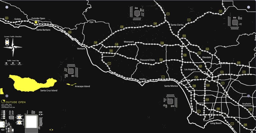
In the lower left corner of the board is the control panel and above that is the direction panel. The ICs located throughout the board are LED matrix drivers which receive commands via I2C from the ESP32S3. The control panel contains the USB-C connector, which communicates with the ESP32S3 via UART at 115200 baud; the ‘Update’ button, which initiates an over the air update; the ‘Restart’ button, which reboots the ESP32S3; and status LED indicators. The direction panel contains the ‘Toggle’ button and LED indicators that show the current traffic direction being displayed — either Southeast or Northwest.
Understanding Road LEDs
Each road LED on the board corresponds to two OpenLR road segments: one northbound, and one southbound. Some road segments cross the coordinates of multiple LEDs, which are all refreshed with a single API call. Version 2 of the device will soon feature configurable LED colors, where the legend of colors is located just below the direction panel. Road segments are classified as fast (always blue or green in version 1) when the segment speed is at least 80% of its normal speed, medium (orange or yellow in version 1) when between 50% and 80%, and slow (red in version 1) when below 50% of its normal speed. Finally, LEDs at intersections of freeways always prioritize showing the segment speed of the freeway oriented most vertically.
LED Indicator States
- Initialization: The traffic direction LEDs are strobing in a loading circle pattern. The device has just been powered on or rebooted, and is initializing the device. This may take longer than expected if there is trouble connecting to the wifi network.
- Configuration change is requested: The error LED is on and the traffic direction LEDs are flashing.
- An OTA update is in progress: The OTA LED is solid white. After updating, the LED will momentarily turn either green or red to indicate update success or failure.
- A server error has occurred: The error LED is flashing. This indicates that data retrieval has failed, and the device may not be displaying live data anymore. This is likely to be resolved the next time the device attempts to retrieve data, otherwise a device reset is recommended.
- A fatal error has occurred: The error LED momentarily turns red, and the device resets. This can happen for a variety of reasons, most likely due to firmware bugs. If this occurs often, a hardware issue may exist, in which case
Configuration Changes
The user can change which wifi network the device attempts to connect to through a 115200 baud UART menu exposed via the USB-C connector. The menu is opened by holding the “Toggle” button (until the menu is opened) and pressing the “Restart” button. The menu is active when the error LED is on and the traffic LEDs are flashing. If you are having trouble accessing the menu, please be sure to hold the “Toggle” button until these indicators are active. The device will request input, during which it is important to remember that BACKSPACE is not supported. If something is incorrect, reopen the menu with the given button combination. Once configuration is complete, the device will reset.
Versioning & Troubleshooting
Boards have a particular hardware version, denoted Vx_x, and firmware version, denoted vx.x.x. Firmware updates are currently mandatory and update availability is checked during a reset and at 12AM, 11AM, and 5PM PST/PDT. To check board version, logs can be inspected via a 115200 UART connection through the USB-C connector.
By default, boards present a minimal amount of logging that includes only versioning and fatal error information. Development builds can be flashed onto the device instead if issues require more comprehensive troubleshooting.